
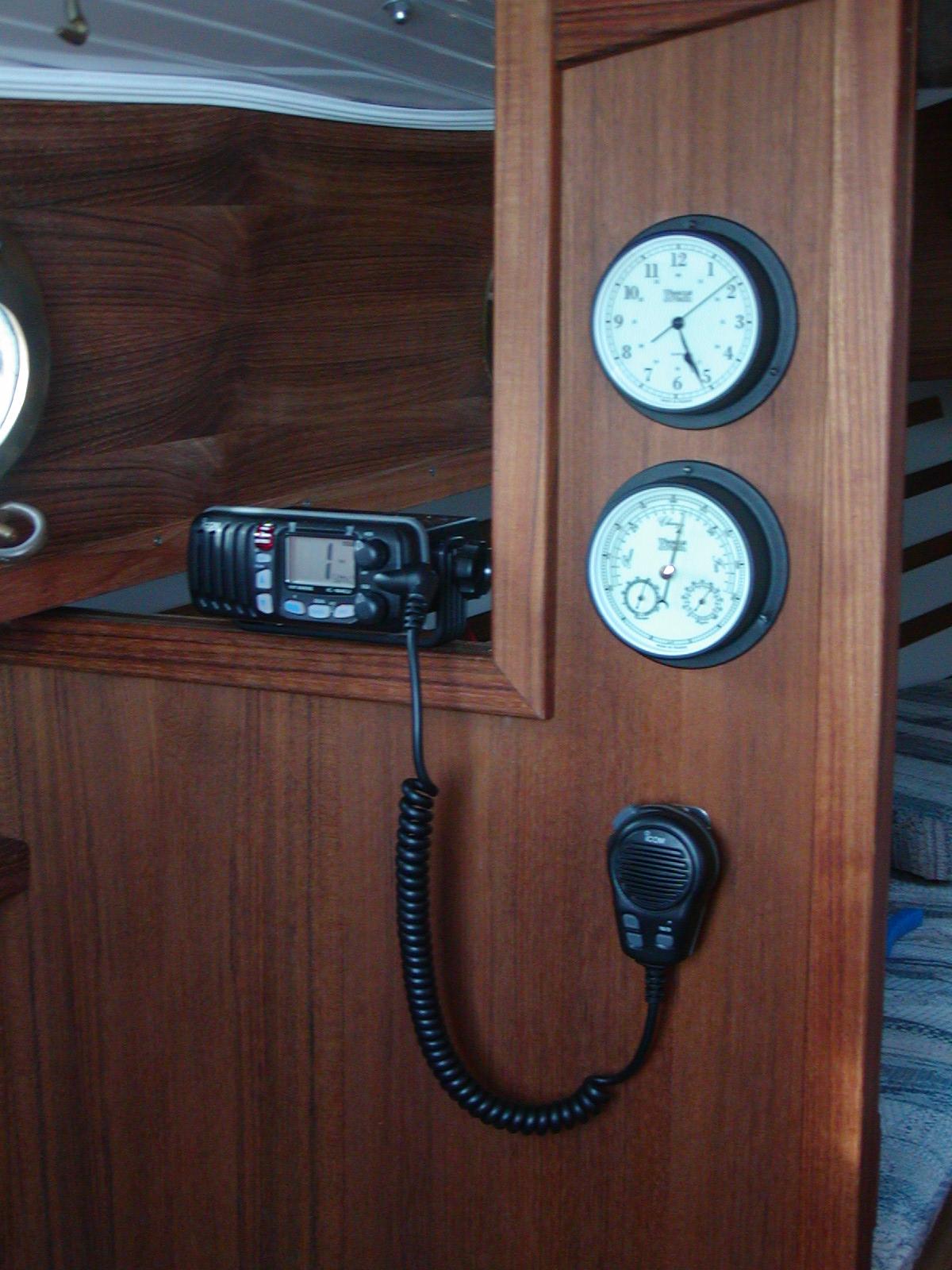

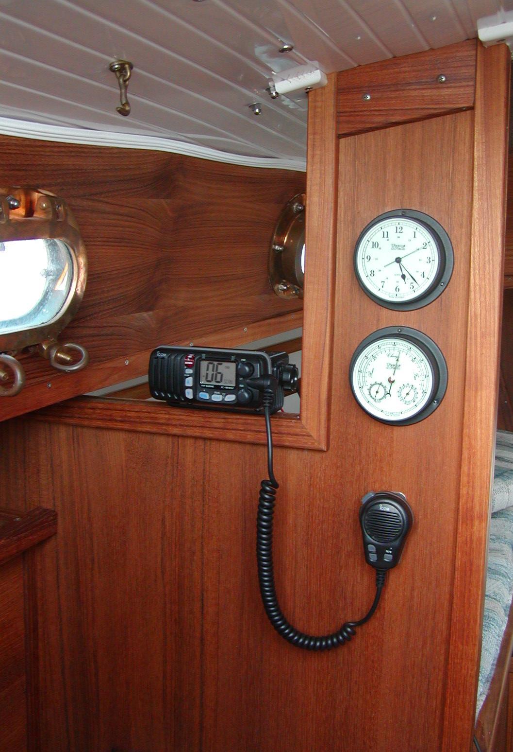
ICOM and Raymarine were among the most likely candidates at the time of purchase in 2001 and the Icom M402 was selected. I also got the optional Command Mic which is mounted in the cockpit and is a real convenience.
Part of the installation was putting a hole in the cabin roof for the VHF antenna cable. It must be possible to remove the cable at the end of the season when the mast is unstepped. An external connector is undesireable due to the possibility of water intrusion and corrosion. The initial solution was to mount two wire seals on a small teak board and remove the board when the mast is unstepped. This leaves the reamining teak work and two holes in the cabin top during haulout. This was replaced later to avoid leaving the hole in the cabin top during haul out and to reduce corrosion problems in the mast wire connector when the mast is stored outside. See mast electrical below.
This job consists of adding a masthead light, masthead fly and light, VHF antenna and cable and replacing the bow light (steaming light) connection.
The initial work on the masthead itself was completed over the winter of 2001/2002. This included drilling and mounting hardware to the masthead and the masthead wiring. In the spring of 2002 the wires were run down the mast. Using 5 conductor wire, two were used for ground wires, and one ground was split either where the bow light attaches to the mid mast.
The hard part was providing the wire entrance to the cabin. A small low teak box was mounted on the cabin top. As initially installed the top of the box is removable. The wires are run through two waterproof wire seals on this top. The top is removed when the mast is unstepped. This allows the wire seals to be left in place and allows the VHF connector to be left in place.
Each winter the VHF wire corroded from being exposed when the mast was stored outside and the connector was not in the cabin. Attempts to cover it with a plastic bad were marginally successfull at best. That meant that each spring a new connecter was needed and a foot or more was cut off the wire.
In 2005 about 3 feet of VHF wire was cut off to get to wire that was not corroded. A new PL-259 connector was soldered on. A female/female barrel was connected to this with a cap on the exposed end of the barrel when in winter storage. The mast wire connector and barrel were protected with heat shrink tubing (such that the tubing must be cut to dissassemble). Inside the cabin a 6' cable goes from the radio to the wire entry on the cabin top where it is connected to the barrel when the mast is in place. Instead of having a removable top to the cabin top teak box the top is now permanent and a watertight cam shell is used.
The interior needs some work to better hide the wires, but that will be listed as another job and taken on some time later.

Initially I had no intention to install an inverter but I picked up a Prowatt 600 when they were steeply discounted at the end of the 2002 sailing season. The inverter can draw quite a lot of current and is intolerant to voltage drop and therefore requires very short 4 gauge wiring. Except for the need for a very short wire run the inverter was very easy to install. I have it on a 80 Amp fuse. It has come in handy when I wanted to use the electric drill on the water. This has already made installing a few other projects easier. The inverter was put to immediate use dirlling the hole for the fixed VHF command mic in the cockpit. Prior to this the hand drill was used but it was only suitable for small holes such as predrilling screw holes.
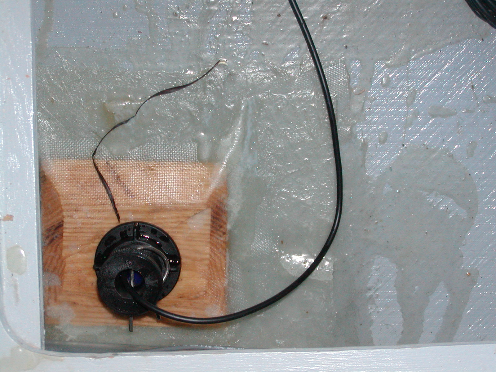
The Navman depth and speed transducers were a standard installation except that the intended hole size was 42mm. Navman is a New Zealand company and the Kiwis use metric. The closest size hole saw available in the US is 1-11/16 which is also very hard to find. For $25 is was able to get a 1-11/16 carbide tipped hole saw from a mail order industrial tool supplier.
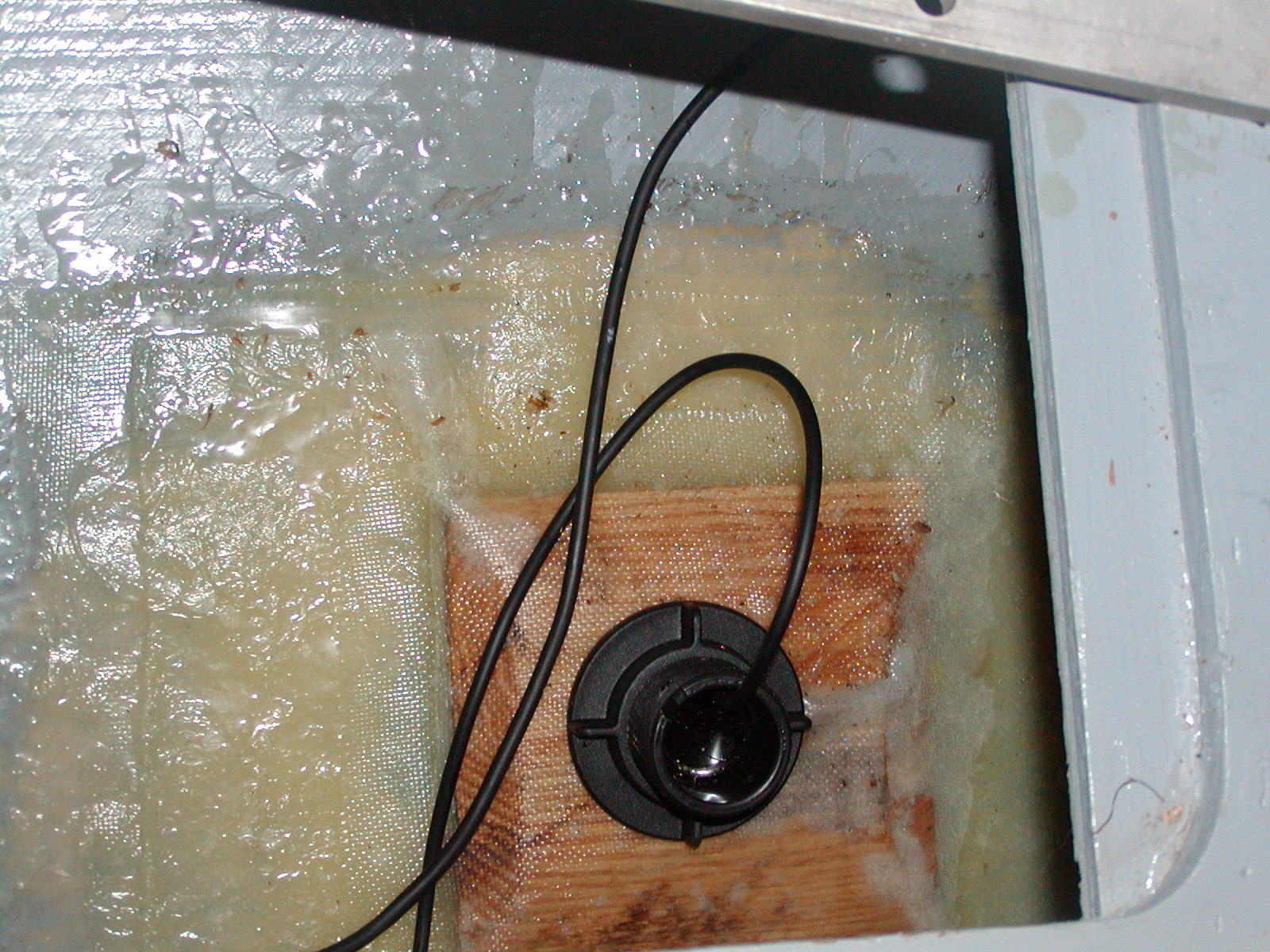
The two transducers were place at about the middle of the hull fore and aft and as close to the centerline as possible on either side. This put them in the openning under the pilot berth as close to the cockpit sole as possible. This is also just inside the trailer bunk rails. The depth transducer was put on the port side and the speed/temperature transducer was put on the starboard side.
First a small then a large pilot hole was drilled. Then paint was removed from the inside of the hull with a paint stripper, rag, and spatula. A respirator was definitely needed for this and used plus fans in the cabin for ventillation. The next step was to rough the surface with 60 grit sandpaper. A backing board was made of 1/2 inch oak, tapered using the table saw such that about a 3 inch square was on the top of an 8 inch square board.
The board was applied inside layers of fiberglass mat and cloth in epoxy resin. The layup was 12 inch square mat, 12 inch square cloth, 8 inch square mat, board, 12 inch square mat, 12 inch square cloth.
The display head installation was very easy. The transducers just plug in. The power and signal wires are an annoying bundle of 24 gauge wire (not even 22 gauge). I put 18-22 ring terminals on each except the ground (because I ran out of small ring terminals) which I just crimped onto a 18-22/14-16 step down butt connector.
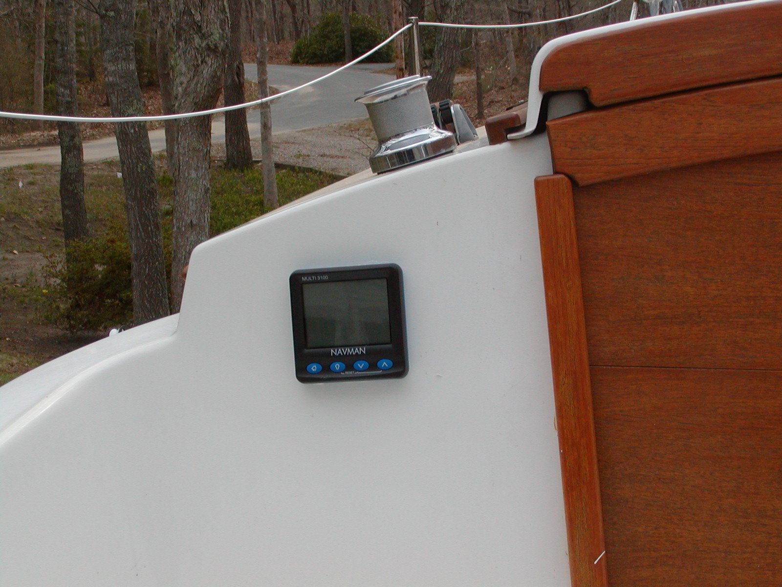
Unfortunately the display head that I got was intermittent. The speed initially didn't work but the depth did. I removed the speed transducer and spun the wheel by hand and got a reading. I put it back but on the water it again didn't work. I took it out and spun it but this time it didn't work. A short time later the depth stopped working. I called Navman and returned the display head. A new one arrived in less than 2 weeks and has worked flawlessly ever since.
When the fixed mount GPS was added, the Navman display head was remounted. See below.
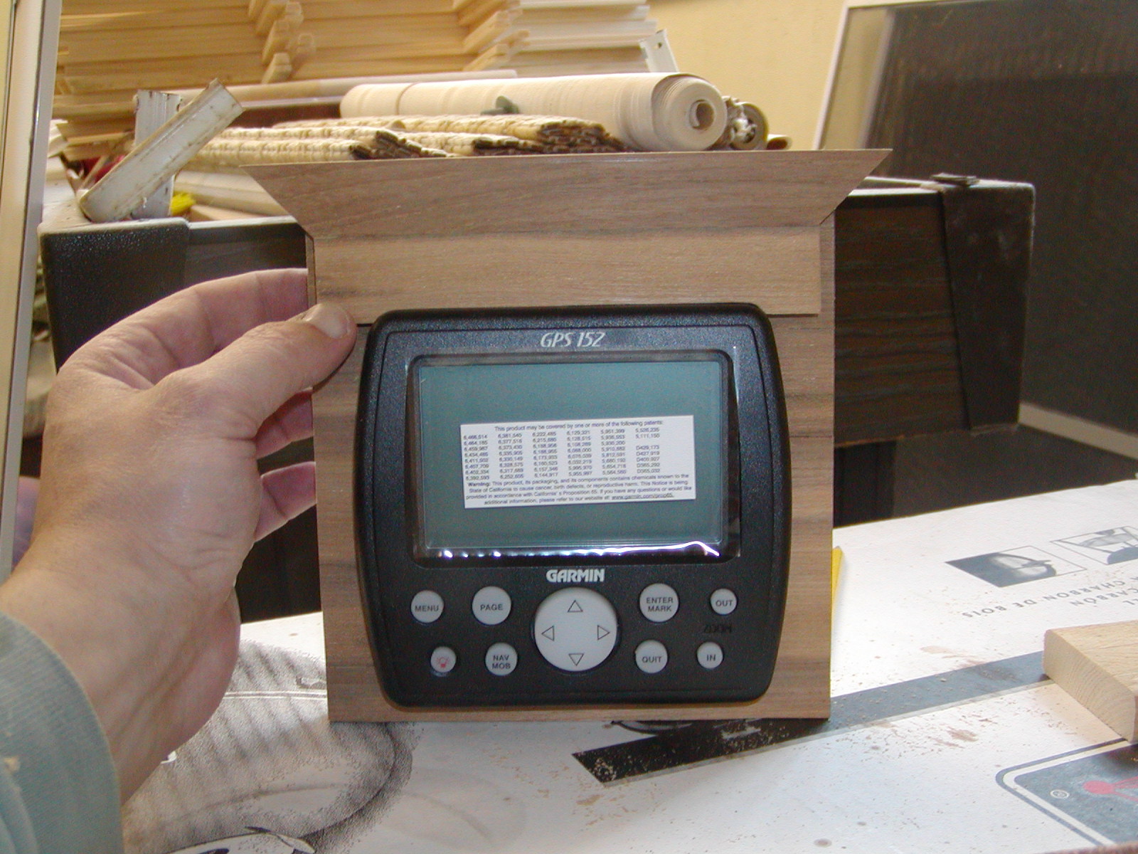
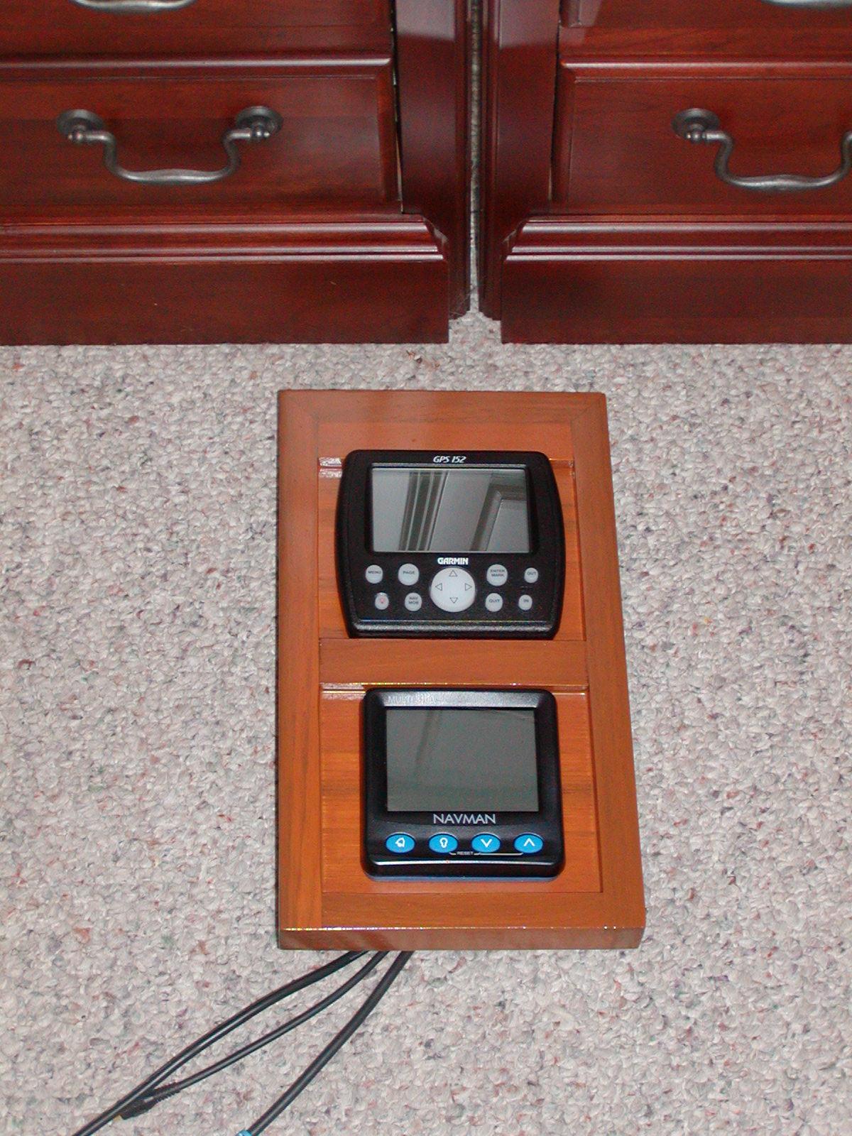
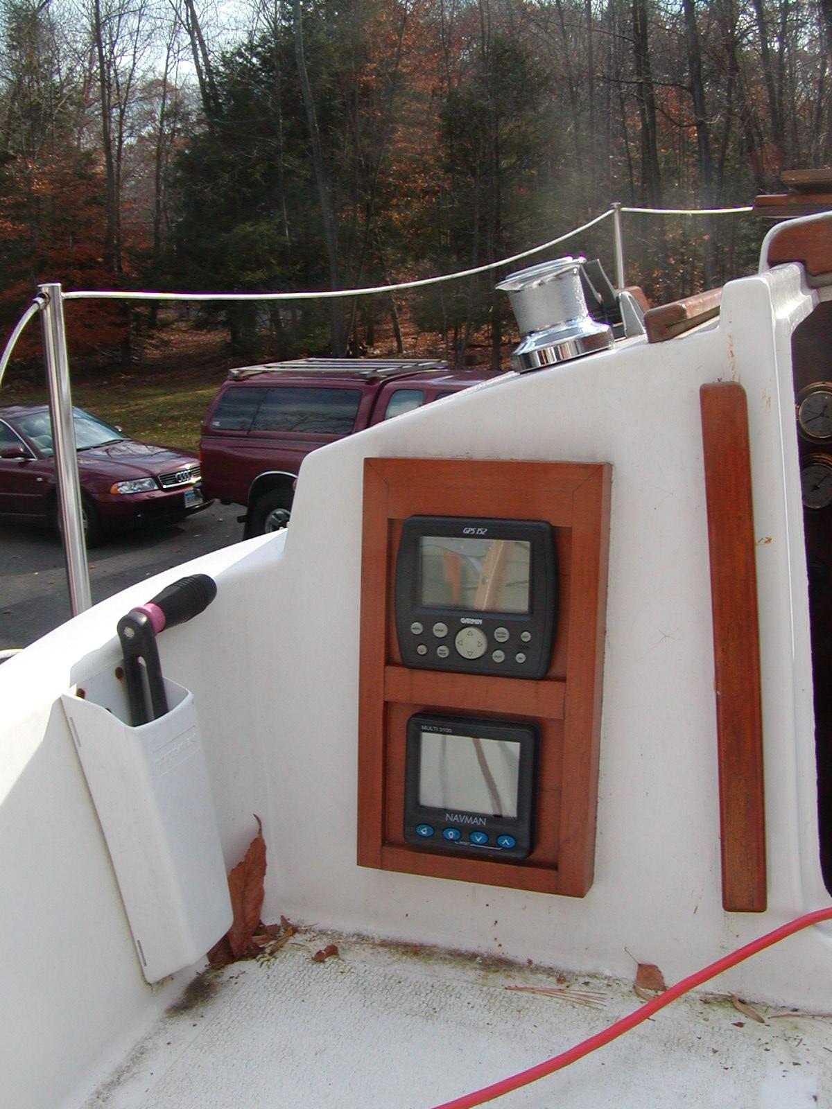
A fixed mount GPS with or without chart plotting capability provides convenience and a degree of redundancy. There are no small batteries to go dead. The handheld then serves as a backup. The Garmin 152 GPS lacks true chartplotting and was available for just over $200 after it was discontinued.
A fixed mount GPS with chart plotting capability provides some convenience. The entry level chart plotter is still rather expensive and the chart kits are very costly. At some later date this GPS may be replaced, but not yet.
NEED PHOTO
An electric horn was added and a FogMate horn controller was added. There is a lot of fog in New England. Chatham is the next town to the south and is famous for its fog. The FogMate horn controller can be set to send horn signals at the recommended interval so that the helmsman doesn't have to do it.
![]() Next Page: Battery, Charging and Propulsion
Next Page: Battery, Charging and Propulsion
![]()